- Üst Kategoriye Dön
- 0
- 1NA kontaklı gövde
- 1NK kontaklı gövde
- Acil Stop Butonu
- Anahtarlı Buton
- BA9s lambalı gövde
- Buton kafası
- Buzzer
- Çiftli Kumanda Butonu
- Işıklı gövde
- Kumanda Butonu
- Parmak İzi Okuyucu
- Seçici Kumanda Butonu
- Sıkma Aparatı
- Sinyal Lamba kafası
- Sinyal Lambası

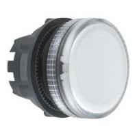

ZB5AV07
- TEKLİF ALINIZ
- ( Karşılaştır )
Ana
|
|||||||||||||||||||||||||||||||||||||||||||||||||||||||||||||||||||||||||||||
Tamamlayıcı
|
|||||||||||||||||||||||||||||||||||||||||||||||||||||||||||||||||||||||||||||
Ortam
|
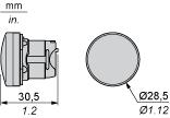
Dimensions

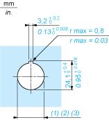
Panel Cut-out for Pushbuttons, Switches and Pilot Lights (Finished Holes, Ready for Installation)Connection by Screw Clamp Terminals or Plug-in Connectors or on Printed Circuit Board

(1)Diameter on finished panel or support(2)For selector switches and Emergency stop buttons, use of an anti-rotation plate type ZB5AZ902 is recommended.(3)Ø22.5 mm recommended (Ø22.3 0+0.4) / Ø0.89 in. recommended (Ø0.88 in. 0+0.016)
Connections | a in mm | a in in. | b in mm | b in in. |
|---|---|---|---|---|
By screw clamp terminals or plug-in connector | 40 | 1.57 | 30 | 1.18 |
By Faston connectors | 45 | 1.77 | 32 | 1.26 |
On printed circuit board | 30 | 1.18 | 30 | 1.18 |

(1)Diameter on finished panel or support(2)For selector switches and Emergency stop buttons, use of an anti-rotation plate type ZB5AZ902 is recommended.(3)Ø22.5 mm recommended (Ø22.3 0+0.4) / Ø0.89 in. recommended (Ø0.88 in. 0+0.016)
Pushbuttons, Switches and Pilot Lights for Printed Circuit Board ConnectionPanel Cut-outs (Viewed from Installers Side)

A:30 mm min. / 1.18 in. min.B:40 mm min. / 1.57 in. min.
Printed Circuit Board Cut-outs (Viewed from Electrical Block Side)Dimensions in mm

A:30 mm min.B:40 mm min.
Dimensions in in.

A:1.18 in. min.B:1.57 in. min.
General Tolerances of the Panel and Printed Circuit BoardThe cumulative tolerance must not exceed 0.3 mm / 0.012 in.: T1 + T2 = 0.3 mm max.
Installation PrecautionsMinimum thickness of circuit board: 1.6 mm / 0.06 in.
Cut-out diameter: 22.4 mm ± 0.1 / 0.88 in. ± 0.004
Orientation of body/fixing collar ZB5AZ009: ± 2°30 (excluding cut-outs marked a and b).
Tightening torque of screws ZBZ006: 0.6 N.m (5.3 lbf.in) max.
Allow for one ZB5AZ079 fixing collar/pillar and its fixing screws:
every 90 mm / 3.54 in. horizontally (X), and 120 mm / 4.72 in. vertically (Y).
with each selector switch head (ZB5AD, ZB5AJ, ZB5AG).
The fixing centers marked a and b are diagonally opposed and must align with those marked 4 and 5.

(1)Head ZB5AD(2)Panel(2)Nut(4)Printed circuit board
Mounting of Adapter (Socket) ZBZ011 2 elongated holes for ZBZ006 screw access
2 1 hole Ø 2.4 mm ± 0.05 / 0.09 in. ± 0.002 for centring adapter ZBZ01
3 8 × Ø 1.2 mm / 0.05 in. holes
4 1 hole Ø 2.9 mm ± 0.05 / 0.11 in. ± 0.002, for aligning the printed circuit board (with cut-out marked a)
5 1 elongated hole for aligning the printed circuit board (with cut-out marked b)
6 4 holes Ø 2.4 mm / 0.09 in. for clipping in adapter ZBZ01
Dimensions An + 18.1 relate to the Ø 2.4 mm ± 0.05 / 0.09 in. ± 0.002 holes for centring adapter ZBZ01.
 |  |  |  |
