| Discrete Input Number | 8 |
|---|
| Discrete Input Type | DI7, DI8 programmable as pulse input: 0…30 kHz, 24 V DC (<= 30 V) |
|---|
| Discrete Input Logic | 16 preset speeds |
|---|
| Discrete Output Number | 0 |
|---|
| Discrete Output Type | Relay outputs R1A, R1B, R1C 250 V AC 3000 mA; Relay outputs R1A, R1B, R1C 30 V DC 3000 mA; Relay outputs R2A, R2C 250 V AC 5000 mA; Relay outputs R2A, R2C 30 V DC 5000 mA; Relay outputs R3A, R3C 250 V AC 5000 mA; Relay outputs R3A, R3C 30 V DC 5000 mA |
|---|
| Analogue Input Number | 3 |
|---|
| Analogue Input Type | AI1, AI2, AI3 software-configurable voltage: 0...10 V DC, impedance: 31.5 kOhm, resolution 12 bits; AI1, AI2, AI3 software-configurable current: 0...20 mA, impedance: 250 Ohm, resolution 12 bits; AI2 voltage analog input: - 10...10 V DC, impedance: 31.5 kOhm, resolution 12 bits |
|---|
| Analogue Output Number | 2 |
|---|
| Analogue Output Type | Software-configurable voltage AQ1, AQ2: 0...10 V DC impedance 470 Ohm, resolution 10 bits; Software-configurable current AQ1, AQ2: 0...20 mA, resolution 10 bits; Software-configurable current DQ-, DQ+: 30 V DC; Software-configurable current DQ-, DQ+: 100 mA |
|---|
| Relay Output Number | 3 |
|---|
| Relay Output Type | Configurable relay logic R1: fault relay NO/NC electrical durability 100000 cycles; Configurable relay logic R2: sequence relay NO electrical durability 100000 cycles; Configurable relay logic R3: sequence relay NO electrical durability 100000 cycles |
|---|
| Maximum Switching Current | Relay output R1, R2, R3 on resistive load, cos phi = 1: 3 A at 250 V AC; Relay output R1, R2, R3 on resistive load, cos phi = 1: 3 A at 30 V DC; Relay output R1, R2, R3 on inductive load, cos phi = 0.4 and L/R = 7 ms: 2 A at 250 V AC; Relay output R1, R2, R3 on inductive load, cos phi = 0.4 and L/R = 7 ms: 2 A at 30 V DC |
|---|
| Minimum Switching Current | Relay output R1, R2, R3: 5 mA at 24 V DC |
|---|
| Network Number Of Phases | 3 phases |
|---|
| Physical Interface | Ethernet; 2-wire RS 485 |
|---|
| Method Of Access | Slave Modbus TCP |
|---|
| Transmission Rate | 10, 100 Mbits; 4800 bps, 9600 bps, 19200 bps, 38.4 Kbps |
|---|
| Transmission Frame | RTU |
|---|
| Output Voltage | <= power supply voltage |
|---|
| Permissible Temporary Current Boost | 1.1 x In during 60 s (normal duty); 1.5 x In during 60 s (heavy duty) |
|---|
| Data Format | 8 bits, configurable odd, even or no parity |
|---|
| Type Of Polarization | No impedance |
|---|
| Frequency Resolution | Display unit: 0.1 Hz; Analog input: 0.012/50 Hz |
|---|
| Electrical Connection | Control: removable screw terminals 0.5...1.5 mm²/20 AWG...16 AWG; Line side: screw terminal 2 x 50...3 x 120 mm²/2 x 1/0 AWG...2 x 300 kcmil; Motor: screw terminal 2 x 50...3 x 120 mm²/2 x 1/0 AWG...2 x 300 kcmil |
|---|
| Connector Type | RJ45 (on the remote graphic terminal) for Ethernet/Modbus TCP; RJ45 (on the remote graphic terminal) for Modbus serial |
|---|
| Exchange Mode | Half duplex, full duplex, autonegotiation Ethernet/Modbus TCP |
|---|
| Number Of Addresses | 1…247 for Modbus serial |
|---|
| Supply | External supply for digital inputs: 24 V DC (19…30 V), <1.25 mA, protection type: overload and short-circuit protection; Internal supply for reference potentiometer (1 to 10 kOhm): 10.5 V DC +/- 5 %, <10 mA, protection type: overload and short-circuit protection; Internal supply for digital inputs and STO: 24 V DC (21…27 V), <200 mA, protection type: overload and short-circuit protection |
|---|
| Local Signalling | 3 LEDs for local diagnostic; 3 LEDs (dual colour) for embedded communication status; 4 LEDs (dual colour) for communication module status; 1 LED (red) for presence of voltage |
|---|
| Input Compatibility | DI1...DI6: discrete input level 1 PLC conforming to IEC 61131-2; DI5, DI6: discrete input level 1 PLC conforming to IEC 65A-68; STOA, STOB: discrete input level 1 PLC conforming to IEC 61131-2 |
|---|
| Sampling Duration | 2 ms +/- 0.5 ms (DI1...DI4) - discrete input; 5 ms +/- 1 ms (DI5, DI6) - discrete input; 5 ms +/- 0.1 ms (AI1, AI2, AI3) - analog input; 10 ms +/- 1 ms (AO1) - analog output |
|---|
| Accuracy | +/- 0.6 % AI1, AI2, AI3 for a temperature variation 60 °C analog input; +/- 1 % AO1, AO2 for a temperature variation 60 °C analog output |
|---|
| Linearity Error | AI1, AI2, AI3: +/- 0.15 % of maximum value for analog input; AO1, AO2: +/- 0.2 % for analog output |
|---|
| Refresh Time | Relay output (R1, R2, R3): 5 ms (+/- 0.5 ms) |
|---|
| Isolation | Between power and control terminals |
|---|
| Discrete And Process Manufacturing | Building - HVAC compressor centrifugal; Food and beverage processing other application; Mining mineral and metal fan; Mining mineral and metal pump; Oil and gas fan; Water and waste water other application; Building - HVAC screw compressor; Food and beverage processing pump; Food and beverage processing fan; Food and beverage processing atomization; Oil and gas electro submersible pump (ESP); Oil |
|---|
| Power Range | 110…220 kW at 380…440 V 3 phases; 110…220 kW at 480…500 V 3 phases |
|---|
| Enclosure Mounting | Wall mounted |
|---|
| 4 Quadrant Operation Possible | False |
|---|
| Asynchronous Motor Control Profile | Constant torque standard; Optimized torque mode; Variable torque standard |
|---|
| Synchronous Motor Control Profile | Permanent magnet motor; Synchronous reluctance motor |
|---|
| Maximum Output Frequency | 500 kHz |
|---|
| Acceleration And Deceleration Ramps | Linear adjustable separately from 0.01...9999 s |
|---|
| Motor Slip Compensation | Adjustable; Can be suppressed; Not available in permanent magnet motor law; Automatic whatever the load |
|---|
| Switching Frequency | 2.5...8 kHz with derating factor; 2...8 kHz adjustable |
|---|
| Nominal Switching Frequency | 2.5 kHz |
|---|
| Braking To Standstill | By DC injection |
|---|
| Brake Chopper Integrated | False |
|---|
| Maximum Input Current | 201.0 A |
|---|
| Maximum Output Voltage | 480.0 V |
|---|
| Apparent Power | 121.8 kVA at 480 V (normal duty); 102.6 kVA at 480 V (heavy duty) |
|---|
| Maximum Transient Current | 232.1 A during 60 s (normal duty); 259.5 A during 60 s (heavy duty) |
|---|
| Network Frequency | 50...60 Hz |
|---|
| Prospective Line Isc | 50 kA |
|---|
| Base Load Current At High Overload | 173.0 A |
|---|
| Base Load Current At Low Overload | 211.0 A |
|---|
| Power Dissipation In W | Forced convection: 2026 W at 380 V, switching frequency 2.5 kHz |
|---|
| With Safety Function Safely Limited Speed (SLS) | False |
|---|
| With Safety Function Safe Brake Management (SBC/SBT) | False |
|---|
| With Safety Function Safe Operating Stop (SOS) | False |
|---|
| With Safety Function Safe Position (SP) | False |
|---|
| With Safety Function Safe Programmable Logic | False |
|---|
| With Safety Function Safe Speed Monitor (SSM) | False |
|---|
| With Safety Function Safe Stop 1 (SS1) | False |
|---|
| With Sft Fct Safe Stop 2 (SS2) | False |
|---|
| With Safety Function Safe Torque Off (STO) | True |
|---|
| With Safety Function Safely Limited Position (SLP) | False |
|---|
| With Safety Function Safe Direction (SDI) | False |
|---|
| Protection Type | Thermal protection: motor; Safe torque off: motor; Motor phase break: motor; Thermal protection: drive; Safe torque off: drive; Overheating: drive; Overcurrent between output phases and earth: drive; Overload of output voltage: drive; Short-circuit protection: drive; Motor phase break: drive; Overvoltages on the DC bus: drive; Line supply overvoltage: drive; Line supply undervoltage: drive; Line s |
|---|
| Quantity Per Set | 1 |
|---|
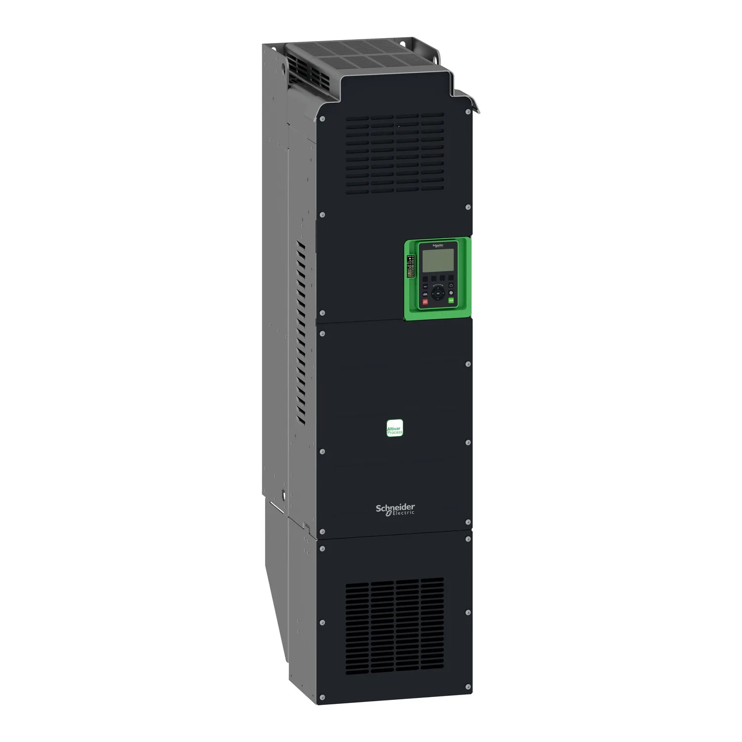
| Width | 320 mm |
|---|
| Height | 852 mm |
|---|
| Depth | 390 mm |
|---|
| Net Weight | 82 kg |
|---|