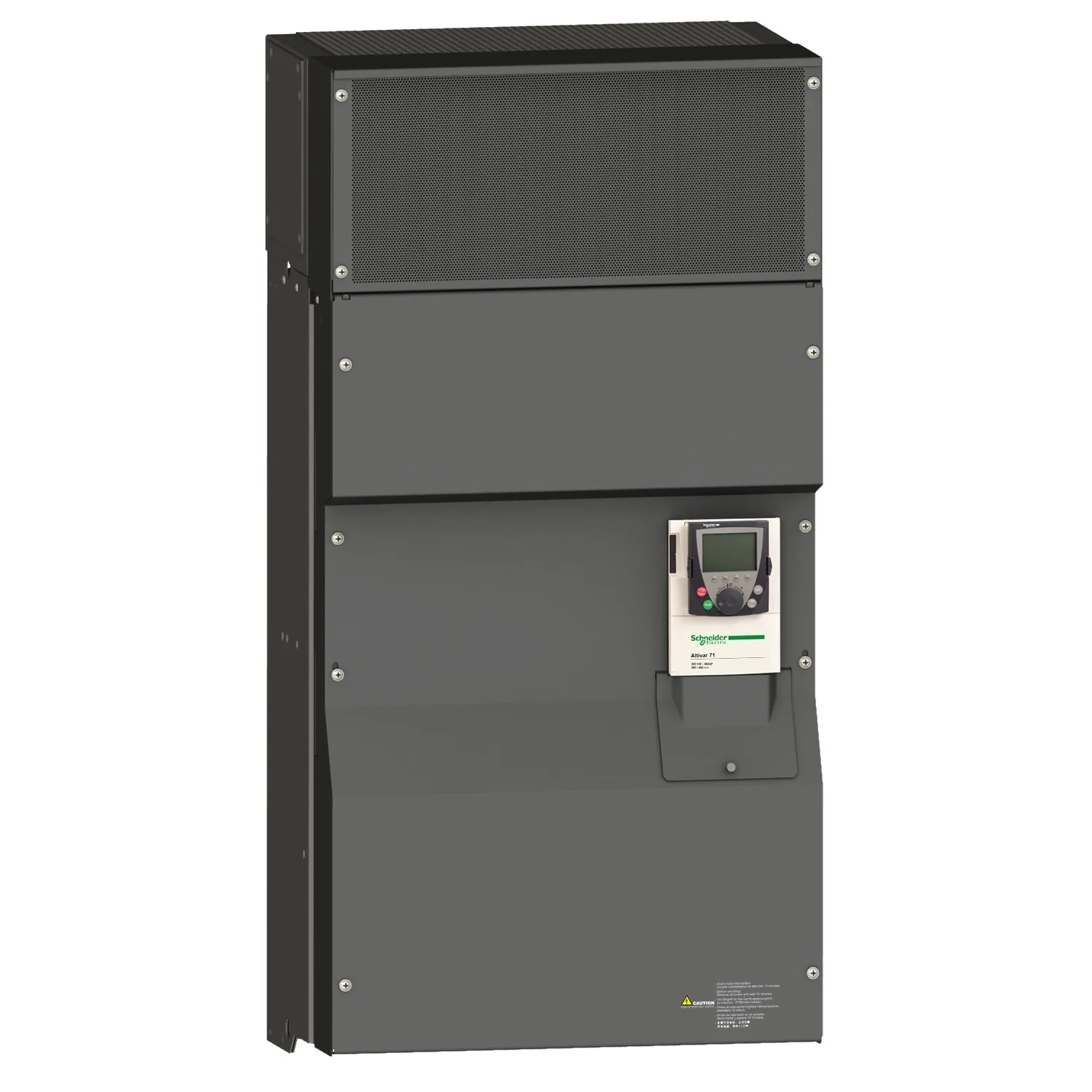
| Product Destination | Synchronous motors; Asynchronous motors |
|---|
| Power Supply Voltage Limits | 323…528 V |
|---|
| Power Supply Frequency | 50...60 Hz - 5...5 % |
|---|
| Power Supply Frequency Limits | 47.5...63 Hz |
|---|
| Speed Range | 1…100 for asynchronous motor in open-loop mode, without speed feedback; 1…1000 for asynchronous motor in closed-loop mode with encoder feedback; 1…50 for synchronous motor in open-loop mode, without speed feedback |
|---|
| Speed Accuracy | +/- 0.01 % of nominal speed in closed-loop mode with encoder feedback 0.2 Tn to Tn; +/- 10 % of nominal slip without speed feedback 0.2 Tn to Tn |
|---|
| Torque Accuracy | +/- 15 % in open-loop mode, without speed feedback; +/- 5 % in closed-loop mode with encoder feedback |
|---|
| Transient Overtorque | 170 % of nominal motor torque +/- 10 % for 60 s every 10 minutes; 220 % of nominal motor torque +/- 10 % for 2 s |
|---|
| Braking Torque | <= 150 % with braking or hoist resistor; 30 % without braking resistor |
|---|
| Synchronous Motor Control Profile | Vector control without speed feedback |
|---|
| Regulation Loop | Adjustable PI regulator |
|---|
| Motor Slip Compensation | Suppressable; Not available in voltage/frequency ratio (2 or 5 points); Adjustable; Automatic whatever the load |
|---|
| Diagnostic | 1 LED (red) for drive voltage |
|---|
| Output Voltage | <= power supply voltage |
|---|
| Insulation | Electrical between power and control |
|---|
| Type Of Cable For Mounting In An Enclosure | With a NEMA Type1 kit: 3 wire(s)UL 508 cable at 40 °C, copper 75 °C / PVC; With an IP21 or an IP31 kit: 3 wire(s)IEC cable at 40 °C, copper 70 °C / PVC; Without mounting kit: 1 wire(s)IEC cable at 45 °C, copper 70 °C / PVC; Without mounting kit: 1 wire(s)IEC cable at 45 °C, copper 90 °C / XLPE/EPR |
|---|
| Electrical Connection | Terminal, clamping capacity: 2.5 mm², 14 AWG (AI1-/AI1+, AI2, AO1, R1A, R1B, R1C, R2A, R2B, LI1...LI6, PWR); Terminal, clamping capacity: 4 x 185 mm² (L1/R, L2/S, L3/T, U/T1, V/T2, W/T3); Terminal, clamping capacity: 4 x 185 mm² (PC/-, PA/+) |
|---|
| Tightening Torque | 0.6 N.m (AI1-/AI1+, AI2, AO1, R1A, R1B, R1C, R2A, R2B, LI1...LI6, PWR); 41 N.m, 360 lb.in (L1/R, L2/S, L3/T, U/T1, V/T2, W/T3); 41 N.m, 360 lb.in (PC/-, PA/+) |
|---|
| Supply | Internal supply for reference potentiometer (1 to 10 kOhm): 10.5 V DC +/- 5 %, <10 mA, protection type: overload and short-circuit protection; Internal supply: 24 V DC (21…27 V), <200 mA, protection type: overload and short-circuit protection |
|---|
| Analogue Input Number | 2 |
|---|
| Analogue Input Type | AI1-/Al1+ bipolar differential voltage: +/- 10 V DC 24 V max, resolution 11 bits + sign; AI2 software-configurable current: 0...20 mA, impedance: 242 Ohm, resolution 11 bits; AI2 software-configurable voltage: 0...10 V DC 24 V max, impedance: 30000 Ohm, resolution 11 bits |
|---|
| Input Sampling Time | 2 ms +/- 0.5 ms (AI1-/Al1+) - analog input(s); 2 ms +/- 0.5 ms (Al2) - analog input(s); 2 ms +/- 0.5 ms (LI1...LI5) - discrete input(s); 2 ms +/- 0.5 ms (LI6)if configured as logic input - discrete input(s) |
|---|
| Response Time | <= 100 ms in STO (Safe Torque Off); AO1 2 ms, tolerance +/- 0.5 ms for analog output(s); R1A, R1B, R1C 7 ms, tolerance +/- 0.5 ms for discrete output(s); R2A, R2B 7 ms, tolerance +/- 0.5 ms for discrete output(s) |
|---|
| Absolute Accuracy Precision | +/- 0.6 % (AI1-/Al1+) for a temperature variation 60 °C; +/- 0.6 % (AI2) for a temperature variation 60 °C; +/- 1 % (AO1) for a temperature variation 60 °C |
|---|
| Linearity Error | +/- 0.15 % of maximum value (AI1-/Al1+, AI2); +/- 0.2 % (AO1) |
|---|
| Analogue Output Number | 1 |
|---|
| Analogue Output Type | AO1 software-configurable logic output 10 V 20 mA; AO1 software-configurable current 0...20 mA, impedance: 500 Ohm, resolution 10 bits; AO1 software-configurable voltage 0...10 V DC, impedance: 470 Ohm, resolution 10 bits |
|---|
| Discrete Output Number | 2 |
|---|
| Discrete Output Type | Configurable relay logic: (R1A, R1B, R1C) NO/NC - 100000 cycles; Configurable relay logic: (R2A, R2B) NO - 100000 cycles |
|---|
| Minimum Switching Current | 3 mA at 24 V DC for configurable relay logic |
|---|
| Maximum Switching Current | R1, R2: 2 A at 250 V AC inductive load, cos phi = 0.4; R1, R2: 2 A at 30 V DC inductive load, cos phi = 0.4; R1, R2: 5 A at 250 V AC resistive load, cos phi = 1; R1, R2: 5 A at 30 V DC resistive load, cos phi = 1 |
|---|
| Discrete Input Number | 7 |
|---|
| Discrete Input Type | LI1...LI5: programmable 24 V DC with level 1 PLC, impedance: 3500 Ohm; LI6: switch-configurable 24 V DC with level 1 PLC, impedance: 3500 Ohm; LI6: switch-configurable PTC probe 0…6, impedance: 1500 Ohm; PWR: safety input 24 V DC, impedance: 1500 Ohm conforming to ISO 13849-1 level d |
|---|
| Discrete Input Logic | Negative logic (sink) (LI1...LI5), > 16 V (state 0), < 10 V (state 1); Positive logic (source) (LI1...LI5), 11 V (state 1); Negative logic (sink) (LI6)if configured as logic input, > 16 V (state 0), < 10 V (state 1); Positive logic (source) (LI6)if configured as logic input, 11 V (state 1) |
|---|
| Acceleration And Deceleration Ramps | S, U or customized; Linear adjustable separately from 0.01 to 9000 s; Automatic adaptation of ramp if braking capacity exceeded, by using resistor |
|---|
| Braking To Standstill | By DC injection |
|---|
| Protection Type | Against exceeding limit speed: drive; Against input phase loss: drive; Break on the control circuit: drive; Input phase breaks: drive; Line supply overvoltage: drive; Line supply undervoltage: drive; Overcurrent between output phases and earth: drive; Overheating protection: drive; Overvoltages on the DC bus: drive; Short-circuit between motor phases: drive; Thermal protection: drive; Motor phase |
|---|
| Insulation Resistance | > 1 mOhm 500 V DC for 1 minute to earth |
|---|
| Frequency Resolution | Analog input: 0.024/50 Hz; Display unit: 0.1 Hz |
|---|
| Communication Port Protocol | CANopen; Modbus |
|---|
| Connector Type | 1 RJ45 (on front face) for Modbus; 1 RJ45 (on terminal) for Modbus; Male SUB-D 9 on RJ45 for CANopen |
|---|
| Physical Interface | 2-wire RS 485 for Modbus |
|---|
| Transmission Frame | RTU for Modbus |
|---|
| Transmission Rate | 4800 bps, 9600 bps, 19200 bps, 38.4 Kbps for Modbus on terminal; 9600 bps, 19200 bps for Modbus on front face; 20 kbps, 50 kbps, 125 kbps, 250 kbps, 500 kbps, 1 Mbps for CANopen |
|---|
| Data Format | 8 bits, 1 stop, even parity for Modbus on front face; 8 bits, odd even or no configurable parity for Modbus on terminal |
|---|
| Number Of Addresses | 1…127 for CANopen; 1…247 for Modbus |
|---|
| Method Of Access | Slave CANopen |
|---|
| Marking | CE |
|---|
| Operating Position | Vertical +/- 10 degree |
|---|
| Height | 1190 mm |
|---|
| Depth | 377 mm |
|---|
| Width | 595 mm |
|---|
| Net Weight | 207 kg |
|---|
| Functionality | Full |
|---|
| Specific Application | Other applications |
|---|
| Option Card | Communication card for CC-Link; Controller inside programmable card; Communication card for DeviceNet; Communication card for EtherNet/IP; Communication card for Fipio; I/O extension card; Communication card for Interbus-S; Interface card for encoder; Communication card for Modbus Plus; Communication card for Modbus TCP; Communication card for Modbus/Uni-Telway; Overhead crane card; Communication |
|---|