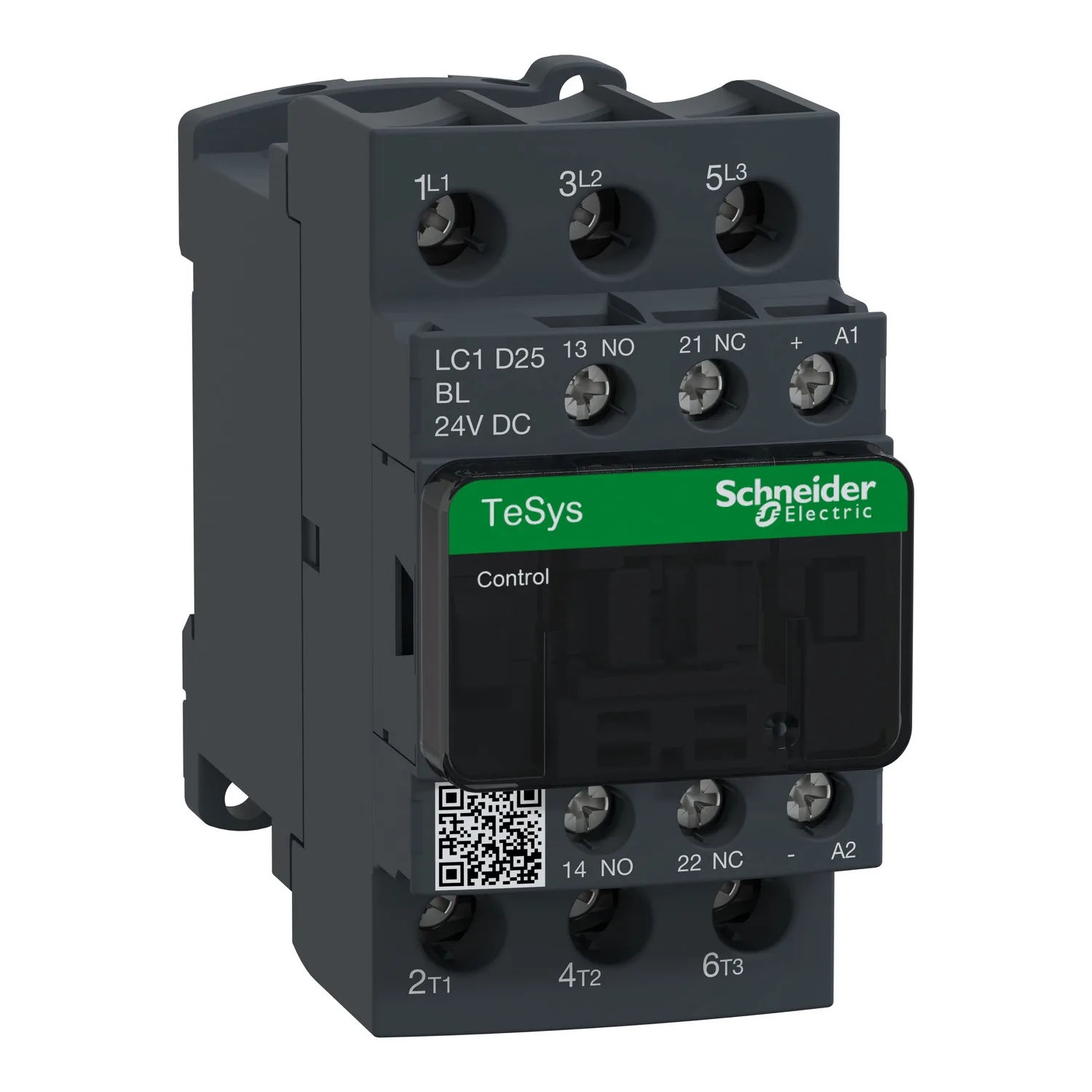
| Motor Power KW | 5.5 kW at 220/230 V AC 50/60 Hz (AC-3); 11 kW at 380/400 V AC 50/60 Hz (AC-3); 11 kW at 415/440 V AC 50/60 Hz (AC-3); 15 kW at 500 V AC 50/60 Hz (AC-3); 15 kW at 660/690 V AC 50/60 Hz (AC-3); 5.5 kW at 220/230 V AC 50/60 Hz (AC-3e); 11 kW at 380/400 V AC 50/60 Hz (AC-3e); 11 kW at 415/440 V AC 50/60 Hz (AC-3e); 15 kW at 500 V AC 50/60 Hz (AC-3e); 15 kW at 660/690 V AC 50/60 Hz (AC-3e); 5.5 kW at 4 |
|---|
| Motor Power Hp | 3 hp at 230/240 V AC 50/60 Hz for 1 phase motors; 2 hp at 115 V AC 50/60 Hz for 1 phase motors; 7.5 hp at 230/240 V AC 50/60 Hz for 3 phases motors; 15 hp at 460/480 V AC 50/60 Hz for 3 phases motors; 20 hp at 575/600 V AC 50/60 Hz for 3 phases motors; 7.5 hp at 200/208 V AC 50/60 Hz for 3 phases motors |
|---|
| Compatibility Code | LC1D |
|---|
| Pole Contact Composition | 3 NO |
|---|
| Protective Cover | With |
|---|
| [Ith] Conventional Free Air Thermal Current | 10 A (at 60 °C) for signalling circuit; 40 A (at 60 °C) for power circuit |
|---|
| Irms Rated Making Capacity | 140 A AC for signalling circuit conforming to IEC 60947-5-1; 250 A DC for signalling circuit conforming to IEC 60947-5-1; 450 A at 440 V for power circuit conforming to IEC 60947 |
|---|
| Rated Breaking Capacity | 450 A at 440 V for power circuit conforming to IEC 60947 |
|---|
| [Icw] Rated Short-time Withstand Current | 240 A 40 °C - 10 s for power circuit; 380 A 40 °C - 1 s for power circuit; 50 A 40 °C - 10 min for power circuit; 120 A 40 °C - 1 min for power circuit; 100 A - 1 s for signalling circuit; 120 A - 500 ms for signalling circuit; 140 A - 100 ms for signalling circuit |
|---|
| Associated Fuse Rating | 10 A gG for signalling circuit conforming to IEC 60947-5-1; 63 A gG at <= 690 V coordination type 1 for power circuit; 40 A gG at <= 690 V coordination type 2 for power circuit |
|---|
| Average Impedance | 2 mOhm - Ith 40 A 50 Hz for power circuit |
|---|
| Power Dissipation Per Pole | 3.2 W AC-1; 1.25 W AC-3; 1.25 W AC-3e |
|---|
| [Ui] Rated Insulation Voltage | Power circuit: 690 V conforming to IEC 60947-4-1; Power circuit: 600 V CSA certified; Power circuit: 600 V UL certified; Signalling circuit: 690 V conforming to IEC 60947-1; Signalling circuit: 600 V CSA certified; Signalling circuit: 600 V UL certified |
|---|
| Overvoltage Category | III |
|---|
| Pollution Degree | 3 |
|---|
| [Uimp] Rated Impulse Withstand Voltage | 6 kV conforming to IEC 60947 |
|---|
| Safety Reliability Level | B10d = 1369863 cycles contactor with nominal load conforming to EN/ISO 13849-1; B10d = 20000000 cycles contactor with mechanical load conforming to EN/ISO 13849-1 |
|---|
| Mechanical Durability | 30 Mcycles |
|---|
| Electrical Durability | 1.65 Mcycles 25 A AC-3 at Ue <= 440 V; 1.4 Mcycles 40 A AC-1 at Ue <= 440 V; 1.65 Mcycles 25 A AC-3e at Ue <= 440 V |
|---|
| Control Circuit Type | DC low consumption |
|---|
| Coil Technology | Built-in bidirectional peak limiting diode suppressor |
|---|
| Control Circuit Voltage Limits | 0.1...0.3 Uc (-40…70 °C):drop-out DC; 0.8...1.25 Uc (-40…60 °C):operational DC; 1...1.25 Uc (60…70 °C):operational DC |
|---|
| Inrush Power In W | 2.4 W (at 20 °C) |
|---|
| Hold-in Power Consumption In W | 2.4 W at 20 °C |
|---|
| Operating Time | 77 ±15 % ms closing; 25 ±20 % ms opening |
|---|
| Time Constant | 40 ms |
|---|
| Maximum Operating Rate | 3600 cyc/h at 60 °C |
|---|
| Connections - Terminals | Control circuit: screw clamp terminals 1 1…4 mm² - cable stiffness: flexible without cable end; Control circuit: screw clamp terminals 2 1…4 mm² - cable stiffness: flexible without cable end; Control circuit: screw clamp terminals 1 1…4 mm² - cable stiffness: flexible with cable end; Control circuit: screw clamp terminals 2 1…2.5 mm² - cable stiffness: flexible with cable end; Control circuit: scr |
|---|
| Tightening Torque | Control circuit: 1.7 N.m - on screw clamp terminals - with screwdriver flat Ø 6 mm; Control circuit: 1.7 N.m - on screw clamp terminals - with screwdriver Philips No 2; Power circuit: 2.5 N.m - on screw clamp terminals - with screwdriver flat Ø 6 mm; Power circuit: 2.5 N.m - on screw clamp terminals - with screwdriver Philips No 2; Control circuit: 1.7 N.m - on screw clamp terminals - with screwdr |
|---|
| Auxiliary Contact Composition | 1 NO + 1 NC |
|---|
| Auxiliary Contacts Type | type mechanically linked 1 NO + 1 NC conforming to IEC 60947-5-1; type mirror contact 1 NC conforming to IEC 60947-4-1 |
|---|
| Signalling Circuit Frequency | 25...400 Hz |
|---|
| Minimum Switching Voltage | 17 V for signalling circuit |
|---|
| Minimum Switching Current | 5 mA for signalling circuit |
|---|
| Insulation Resistance | > 10 MOhm for signalling circuit |
|---|
| Non-overlap Time | 1.5 ms on de-energisation between NC and NO contact; 1.5 ms on energisation between NC and NO contact |
|---|
| Mounting Support | Plate; Rail |
|---|