
Schneider
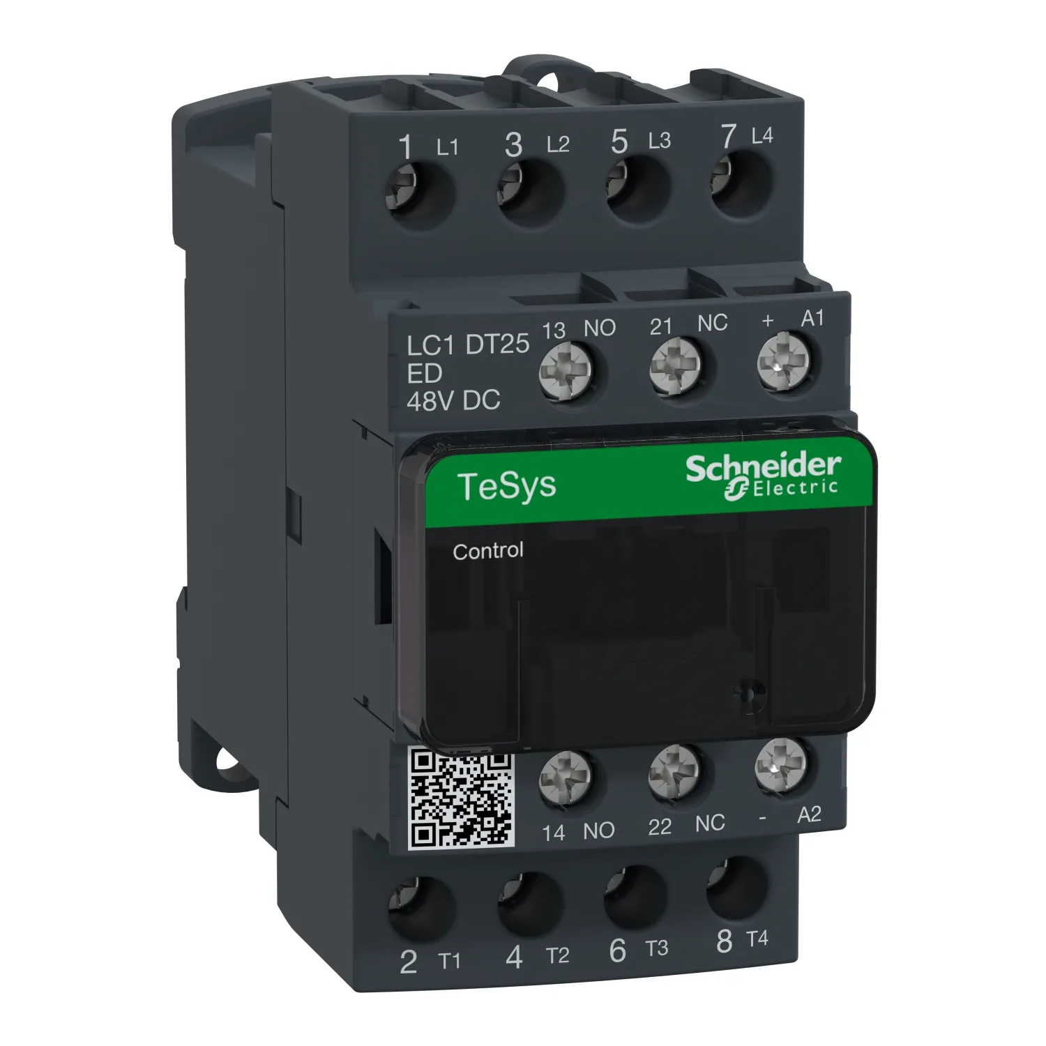
Contactor: 4-pole; NO x4; Auxiliary contacts: NC + NO; 48VDC; 25A
Schneider LC1DT25ED, Contactor: 4-pole; NO x4; Auxiliary contacts: NC + NO; 48VDC; 25A. Category: TeSys Deca Advanced. Request a quote for price and lead time.
- Reference:LC1DT25ED
- Manufacturer / Brand:Schneider
- Availability:On Request / Inquire Stock
- Price:93.60 EUR (Request a quote)
Key Specifications
- Range
- TeSys; TeSys Deca
- Range Of Product
- TeSys Deca Advanced
- Product Or Component Type
- Contactor
- Device Short Name
- LC1D
Product Description
TeSys D contactor, 4 poles (4NO), for non-inductive load applications up to 25A/690V AC-1. It provides a 48V DC coil with transient suppressor module, 1NO+1NC built-in auxiliary contacts (NC mirror certified), connection by screw clamp terminals. For operating rates until 3600 cycles/hour and environments until 60°C, it procures high reliability and durability. Compact (45mm width), DIN-rail mounting or screw fixing. Multi standards certified (IEC, UL, CSA, CCC, EAC, Marine).
Key Features
- "New modern look & feel of all machines"
- "Designed to meet the requirements of industrial and HVAC applications"
- "Easier to install and operate with multi-standard screws"
- "With IEC60335-1 compliance, improved fire resistance, and dustproof auxiliaries"
- "Digital customer experience for technical documents"
Technical Specifications
Main10
| Range | TeSys; TeSys Deca |
|---|---|
| Range Of Product | TeSys Deca Advanced |
| Product Or Component Type | Contactor |
| Device Short Name | LC1D |
| Contactor Application | Resistive load |
| Utilisation Category | AC-1 |
| Poles Description | 4P |
| [Ue] Rated Operational Voltage | Power circuit: <= 690 V AC 25...400 Hz; Power circuit: <= 300 V DC |
| [Ie] Rated Operational Current | 25 A (at <60 °C) at <= 440 V AC AC-1 for power circuit |
| [Uc] Control Circuit Voltage | 48 V DC |
Complementary35
| Compatibility Code | LC1D |
|---|---|
| Pole Contact Composition | 4 NO |
| Protective Cover | With |
| [Ith] Conventional Free Air Thermal Current | 10 A (at 60 °C) for signalling circuit; 25 A (at 60 °C) for power circuit |
| Irms Rated Making Capacity | 140 A AC for signalling circuit conforming to IEC 60947-5-1; 250 A DC for signalling circuit conforming to IEC 60947-5-1; 250 A at 440 V for power circuit conforming to IEC 60947 |
| Rated Breaking Capacity | 250 A at 440 V for power circuit conforming to IEC 60947 |
| [Icw] Rated Short-time Withstand Current | 30 A 40 °C - 10 min for power circuit; 61 A 40 °C - 1 min for power circuit; 105 A 40 °C - 10 s for power circuit; 210 A 40 °C - 1 s for power circuit; 100 A - 1 s for signalling circuit; 120 A - 500 ms for signalling circuit; 140 A - 100 ms for signalling circuit |
| Associated Fuse Rating | 10 A gG for signalling circuit conforming to IEC 60947-5-1; 40 A gG at <= 690 V coordination type 1 for power circuit; 25 A gG at <= 690 V coordination type 2 for power circuit |
| Average Impedance | 2.5 mOhm - Ith 25 A 50 Hz for power circuit |
| Power Dissipation Per Pole | 1.56 W AC-1 |
| [Ui] Rated Insulation Voltage | Power circuit: 600 V CSA certified; Power circuit: 600 V UL certified; Signalling circuit: 690 V conforming to IEC 60947-1; Signalling circuit: 600 V CSA certified; Signalling circuit: 600 V UL certified; Power circuit: 690 V conforming to IEC 60947-4-1 |
| Overvoltage Category | III |
| Pollution Degree | 3 |
| [Uimp] Rated Impulse Withstand Voltage | 6 kV conforming to IEC 60947 |
| Safety Reliability Level | B10d = 1369863 cycles contactor with nominal load conforming to EN/ISO 13849-1; B10d = 20000000 cycles contactor with mechanical load conforming to EN/ISO 13849-1 |
| Mechanical Durability | 30 Mcycles |
| Electrical Durability | 0.8 Mcycles 25 A AC-1 at Ue <= 440 V |
| Control Circuit Type | DC standard |
| Coil Technology | Built-in bidirectional peak limiting diode suppressor |
| Control Circuit Voltage Limits | 0.1...0.25 Uc (-40…70 °C):drop-out DC; 0.7...1.25 Uc (-40…60 °C):operational DC; 1...1.25 Uc (60…70 °C):operational DC |
| Inrush Power In W | 5.4 W (at 20 °C) |
| Hold-in Power Consumption In W | 5.4 W at 20 °C |
| Operating Time | 20 ±20 % ms opening; 63 ±15 % ms closing |
| Time Constant | 28 ms |
| Maximum Operating Rate | 3600 cyc/h at 60 °C |
| Connections - Terminals | Control circuit: screw clamp terminals 2 1…2.5 mm² - cable stiffness: flexible with cable end; Control circuit: screw clamp terminals 1 1…4 mm² - cable stiffness: flexible without cable end; Control circuit: screw clamp terminals 2 1…4 mm² - cable stiffness: flexible without cable end; Control circuit: screw clamp terminals 1 1…4 mm² - cable stiffness: flexible with cable end; Control circuit: scr |
| Tightening Torque | Control circuit: 1.7 N.m - on screw clamp terminals - with screwdriver flat Ø 6 mm; Control circuit: 1.7 N.m - on screw clamp terminals - with screwdriver Philips No 2; Power circuit: 1.7 N.m - on screw clamp terminals - with screwdriver flat Ø 6 mm; Power circuit: 1.7 N.m - on screw clamp terminals - with screwdriver Philips No 2; Control circuit: 1.7 N.m - on screw clamp terminals - with screwdr |
| Auxiliary Contact Composition | 1 NO + 1 NC |
| Auxiliary Contacts Type | type mechanically linked 1 NO + 1 NC conforming to IEC 60947-5-1; type mirror contact 1 NC conforming to IEC 60947-4-1 |
| Signalling Circuit Frequency | 25...400 Hz |
| Minimum Switching Voltage | 17 V for signalling circuit |
| Minimum Switching Current | 5 mA for signalling circuit |
| Insulation Resistance | > 10 MOhm for signalling circuit |
| Non-overlap Time | 1.5 ms on de-energisation between NC and NO contact; 1.5 ms on energisation between NC and NO contact |
| Mounting Support | Rail; Plate |
Environment14
| Standards | CSA C22.2 No 14; EN 60947-4-1; EN 60947-5-1; IEC 60947-4-1; IEC 60947-5-1; UL 60947-4-1; IEC 60335-1 |
|---|---|
| Product Certifications | DNV; GL; CCC; LROS (Lloyds register of shipping); RINA; BV; GOST; UL; CSA; CB |
| IP Degree Of Protection | IP20 front face conforming to IEC 60529 |
| Protective Treatment | TH conforming to IEC 60068-2-30 |
| Climatic Withstand | conforming to IACS E10 exposure to damp heat; conforming to IEC 60947-1 Annex Q category D exposure to damp heat |
| Permissible Ambient Air Temperature Around The Device | -40…60 °C; 60…70 °C with derating |
| Operating Altitude | 0...3000 m |
| Fire Resistance | 850 °C conforming to IEC 60695-2-1 |
| Flame Retardance | V1 conforming to UL 94 |
| Mechanical Robustness | Vibrations contactor open (2 Gn, 5...300 Hz); Vibrations contactor closed (4 Gn, 5...300 Hz); Shocks contactor closed (15 Gn for 11 ms); Shocks contactor open (10 Gn for 11 ms) |
| Height | 85 mm |
| Width | 45 mm |
| Depth | 99 mm |
| Net Weight | 0.365 kg |
Packing Units12
| Unit Type Of Package 1 | PCE |
|---|---|
| Number Of Units In Package 1 | 1 |
| Package 1 Height | 5.500 cm |
| Package 1 Width | 9.500 cm |
| Package 1 Length | 11.800 cm |
| Package 1 Weight | 553.000 g |
| Unit Type Of Package 2 | S02 |
| Number Of Units In Package 2 | 16 |
| Package 2 Height | 15.000 cm |
| Package 2 Width | 30.000 cm |
| Package 2 Length | 40.000 cm |
| Package 2 Weight | 9.338 kg |
Logistical informations1
| Country Of Origin | ID |
|---|
Contractual warranty1
| Warranty (in Months) | 18 |
|---|
Documents and Downloads
Documents are published by the manufacturer and open in a new tab.