
Schneider
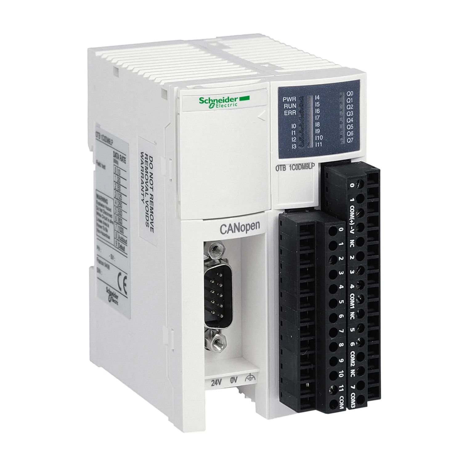
I/O distributed module OTB - CANopen bus - 0..1000 m
Not for sale
Schneider OTB1C0DM9LP, I/O distributed module OTB - CANopen bus - 0..1000 m. Category: Advantys OTB. Not for sale; no price or quote is offered for this product.
- Reference:OTB1C0DM9LP
- Manufacturer / Brand:Schneider
Key Specifications
- Range Of Product
- Modicon OTB
- Product Or Component Type
- I/O distributed module
- Discrete Input Number
- 12 conforming to EN/IEC 61131 type 1
- Discrete Input Logic
- Sink or source
Product Description
Distributed I/O Module Otb - Canopen Bus - 0..1000 M
Technical Specifications
Main9
| Range Of Product | Modicon OTB |
|---|---|
| Product Or Component Type | I/O distributed module |
| Integrated Connection Type | CANopen bus SUB-D 9, transmission mode: 2 twisted shielded pairs at 10 kbit/s...1 Mbit/s |
| Bus Type | CANopen S20, profile: DS 401 V2.1, method of access: CSMA/MA multimaster with priority conforming to DR303-2; CANopen S20, profile: DS 401 V2.1, method of access: CSMA/MA multimaster with priority conforming to DS301 V4.02 |
| Discrete Input Number | 12 conforming to EN/IEC 61131 type 1 |
| Discrete Input Logic | Sink or source |
| Discrete Input Current | 5 mA for I0...I1; 5 mA for I6...I7; 7 mA for I2...I5; 7 mA for I8...I11 |
| Discrete Output Number | 2 solid state PNP for Q0...Q1 output logic: source; 6 relay for Q2...Q7 |
| Discrete Output Current | 2000 mA for relay; 300 mA for solid state |
Complementary48
| Topology | Devices linked by daisy-chaining or tap junctions |
|---|---|
| Number Of Server Device(s) | 63 |
| Bus Length | 0…100 m tap-off length: 0…10 m, 500 kbit/s; 0…1000 m tap-off length: 0…120 m, 50 kbit/s; 0…250 m tap-off length: 0…10 m, 250 kbit/s; 0…2500 m tap-off length: 0…300 m, 20 kbit/s; 0…40 m tap-off length: 0…6 m, 800 kbit/s; 0…500 m tap-off length: 0…10 m, 125 kbit/s; 0…5000 m tap-off length: 0…600 m, 10 kbit/s; 0…20 m, 1 Mbit/s |
| Number Of Devices Per Segment | 0…16, length of segment <205 m; 0…32, length of segment <185 m; 0…64, length of segment <160 m |
| Discrete Input Voltage | 24 V |
| Discrete Input Voltage Type | DC |
| Discrete Input Type | NPN or PNP |
| Input Voltage Limits | 20.4...26.4 V |
| Electronic Filtering Time | 0.035 ms for I0...I1 at state 1; 0.035 ms for I6...I7 at state 1; 0.04 ms for I2...I5 at state 1; 0.04 ms for I8...I11 at state 1; 0.045 ms for I0...I1 at state 0; 0.045 ms for I6...I7 at state 0; 0.15 ms for I2...I5 at state 0; 0.15 ms for I8...I11 at state 0 |
| Configurable Filtering Time | 12 ms; 0 ms; 3 ms |
| Input Impedance | 3.4 kOhm for I2...I5; 3.4 kOhm for I8...I11; 5.7 kOhm for I0...I1; 5.7 kOhm for I6...I7 |
| Discrete Output Voltage | 24 V DC solid state output(s); 240 V AC relay output(s); 30 V DC relay output(s) |
| Output Voltage Limits | 20.4...28.8 V solid state |
| Maximum Output Current | 360 mA, solid state |
| Maximum Current Per Output Common | 8 A relay; 0.72 A solid state |
| Current Consumption | 30 mA at 5 V DC (at state 1) relay output; 40 mA at 24 V DC (at state 1) relay output; 5 mA at 5 V DC (at state 0) relay output |
| Output Overvoltage Protection | 38...40 V |
| Maximum Tungsten Load | <8 W for solid state |
| Response Time | 300 µs at state 0 for relay; 300 µs at state 1 for relay; 5 µs at state 0 for solid state; 5 µs at state 1 for solid state |
| Minimum Switchable Load | 0.1 mA |
| Contact Bounce Time | <= 1 ms for relay |
| Maximum Leakage Current | 0.1 mA at state 0 for solid state |
| Drop-out Voltage | 1 V at state 1 |
| Insulation Between Channel And Internal Logic | 1500 Vrms for 1 minute for relay output; 500 Vrms for 1 minute for input circuit; 500 Vrms for 1 minute for solid state output |
| Insulation Between Channels | None |
| Contact Resistance | 30 mOhm |
| Electrical Durability | 500000 cycles AC-1 with 500 VA load for relay output; 500000 cycles AC-14 with 250 VA load for relay output; 500000 cycles AC-15 with 200 VA load for relay output; 500000 cycles DC-1 with 60 W load for relay output; 500000 cycles DC-13 with 30 W load for relay output |
| Supply Circuit Type | DC |
| [Us] Rated Supply Voltage | 24 V |
| Supply Voltage Limits | 20.4…26.2 V |
| Input Current | 700 mA at 26.2 V for supply circuit |
| Inrush Current | 1 A for solid state output; 50 A for supply circuit |
| Power Consumption In W | 19 W |
| Maximum Number Of I/O Expansion Module | 7 |
| I/O Expansion Capacity | 132 with screw terminal discrete I/O module(s); 188 with spring terminal discrete I/O module(s); 244 with HE10 connector discrete I/O module(s); 7 x 8I or 7 x 2I or 7 x (4I/2O) with screw terminal analogue I/O module(s) |
| Insulation Resistance | >= 10 MOhm between I/O and earth terminals; >= 10 MOhm between power supply and earth |
| I/O Connection | Removable screw terminal block |
| Number Of Common Point | 1 for relay output (1 NO); 1 for relay output (2 NO); 1 for relay output (3 NO); 1 for input; 1 for solid state output |
| Counting Input Number | 2 |
| Counting Capacity | 32 bits |
| Counting Frequency | 20000 Hz; 5000 Hz |
| Pulse Generator Number | 2 |
| Pulse Generator Frequency | 7 kHz |
| Pulse Generator Function | RPWM pulse width modulation; RPLS pulse generator output |
| Marking | CE |
| Fixing Mode | By clips (35 mm symmetrical DIN rail); By screws (panel with fixing kit); By screws (solid plate with fixing kit) |
| Status LED | 1 LED per channel (green) I/O; 1 LED (green) PWR; 1 LED (green) RUN; 1 LED (red) ERR |
| Net Weight | 0.195 kg |
Environment16
| IP Degree Of Protection | IP20 |
|---|---|
| Immunity To Microbreaks | 10 ms for supply circuit |
| Dielectric Strength | 500 V between I/O and earth terminals; 500 V between power supply and earth |
| Standards | CSA; UL 508; EN 61131-2; CSA C22.2 No 213 Class I Division 2 Group D; CSA C22.2 No 213 Class I Division 2 Group B; CSA C22.2 No 213 Class I Division 2 Group A; IEC 61131-2; CSA C22.2 No 213 Class I Division 2 Group C |
| Product Certifications | cULus |
| Ambient Air Temperature For Operation | 0…55 °C |
| Ambient Air Temperature For Storage | -25…70 °C |
| Relative Humidity | 30…95 % without condensation |
| Pollution Degree | 2 conforming to EN 60664; 2 conforming to IEC 60664 |
| Operating Altitude | 0...2000 m |
| Storage Altitude | 0…3000 m |
| Vibration Resistance | 0.075 mm at 10…57 Hz on 35 mm symmetrical DIN rail; 1 gn at 57…150 Hz on 35 mm symmetrical DIN rail |
| Shock Resistance | 15 gn for 11 ms conforming to EN 61131; 15 gn for 11 ms conforming to IEC 61131 |
| Resistance To Electrostatic Discharge | 4 kV in contact conforming to IEC 61000-4-2; 8 kV in air conforming to EN 61000-4-2; 8 kV in air conforming to IEC 61000-4-2; 4 kV in contact conforming to EN 61000-4-2 |
| Resistance To Radiated Fields | 10 V/m, radio frequency fields = 80000000…2000000000 Hz conforming to EN 61000-4-3; 10 V/m, radio frequency fields = 80000000…2000000000 Hz conforming to IEC 61000-4-3 |
| Resistance To Fast Transients | 1 kV (24 V solid state I/O) conforming to IEC 61000-4-4; 2 kV (24 V supply) conforming to IEC 61000-4-4 |
Packing Units12
| Unit Type Of Package 1 | PCE |
|---|---|
| Number Of Units In Package 1 | 1 |
| Package 1 Height | 7.5 cm |
| Package 1 Width | 10.5 cm |
| Package 1 Length | 13.0 cm |
| Package 1 Weight | 308.0 g |
| Unit Type Of Package 2 | S03 |
| Number Of Units In Package 2 | 18 |
| Package 2 Height | 30.0 cm |
| Package 2 Width | 30.0 cm |
| Package 2 Length | 40.0 cm |
| Package 2 Weight | 6.057 kg |
Logistical informations1
| Country Of Origin | FR |
|---|
Contractual warranty1
| Warranty (in Months) | 18 |
|---|
Documents and Downloads
Documents are published by the manufacturer and open in a new tab.